Industry Challenges: Why Aluminum Silicon Alloy Demands a Different Approach
A Two-Phase Composite, Not a Uniform Metal
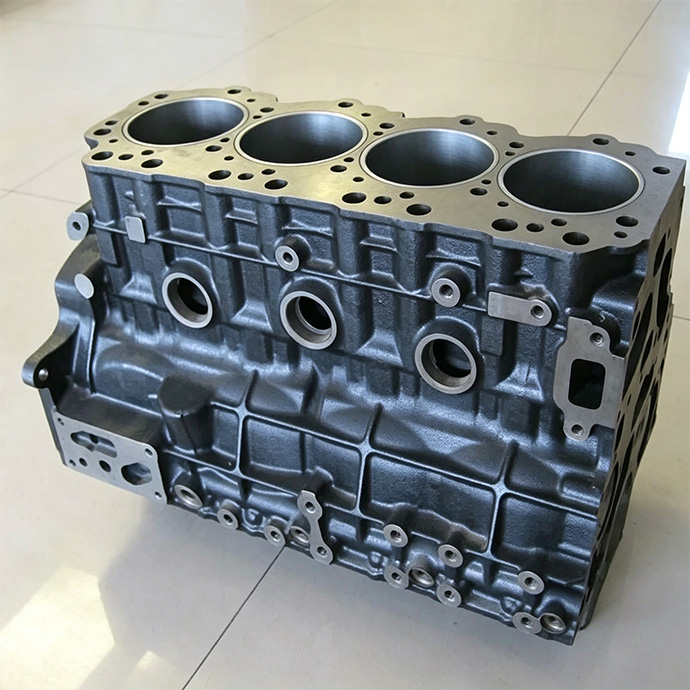
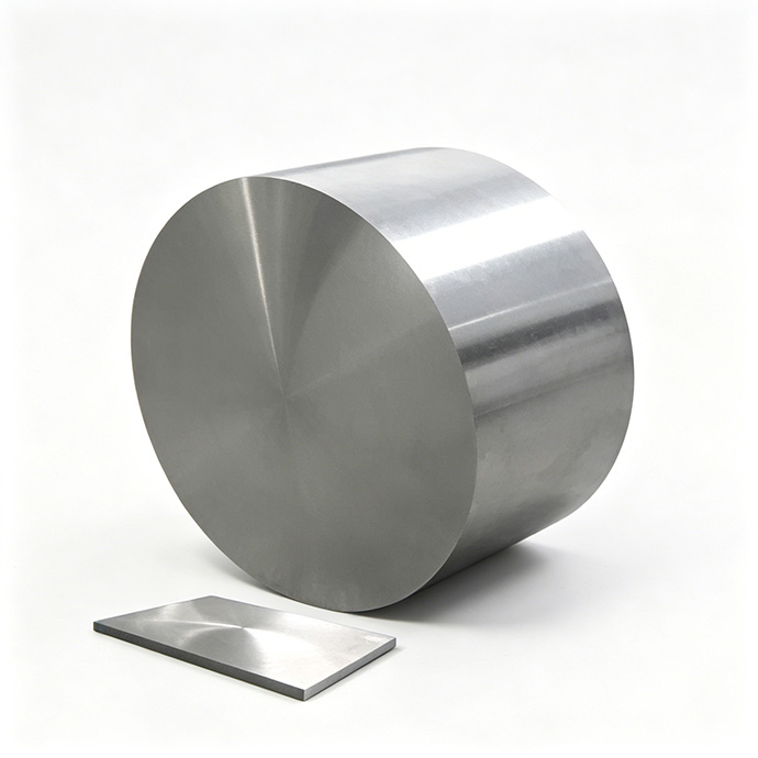
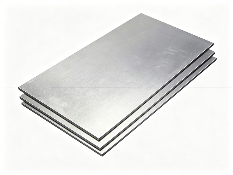
Aluminum silicon alloy is a composite at the microstructural level. A soft, ductile aluminum matrix surrounds hard, brittle silicon particles that often exceed 20% of the material. This dual-phase structure gives the alloy its light weight and wear resistance — and makes it exceptionally difficult to cut.
Every cut alternates between soft aluminum and hard silicon. The aluminum smears and tears. The silicon resists and abrades the tool edge. You cannot optimize for one phase without sacrificing the other. A tool hard enough for silicon chips against aluminum. A tool tough enough for aluminum dulls instantly on silicon. This is not a parameter problem — it is built into the material.
Four Problems That Show Up in Your Production
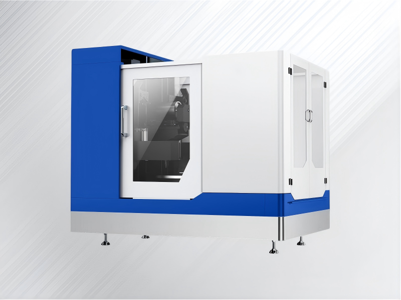
Our Solution: The Zelatec Diamond Wire Sawing Ecosystem
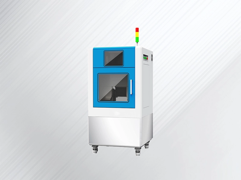
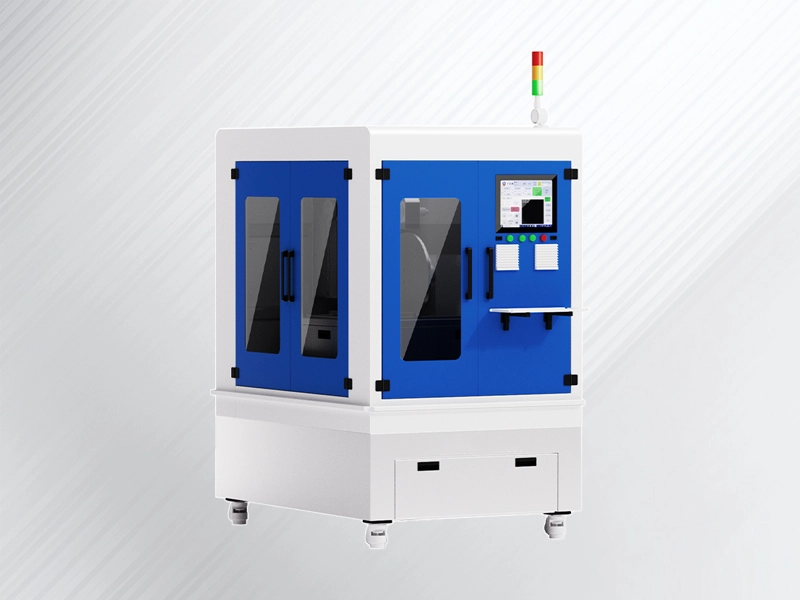
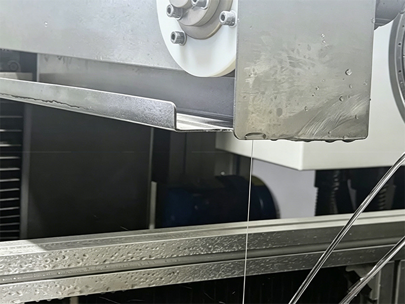
Zelatec delivers more than just equipment; we provide a high-precision Endless Diamond Wire Sawing Ecosystem engineered to master the “Soft-Hard” complexity of Aluminum Silicon alloys. By replacing traditional mechanical “tearing” with our advanced high-speed grinding mechanism, we ensure your production moves from “standard” to “superior.”
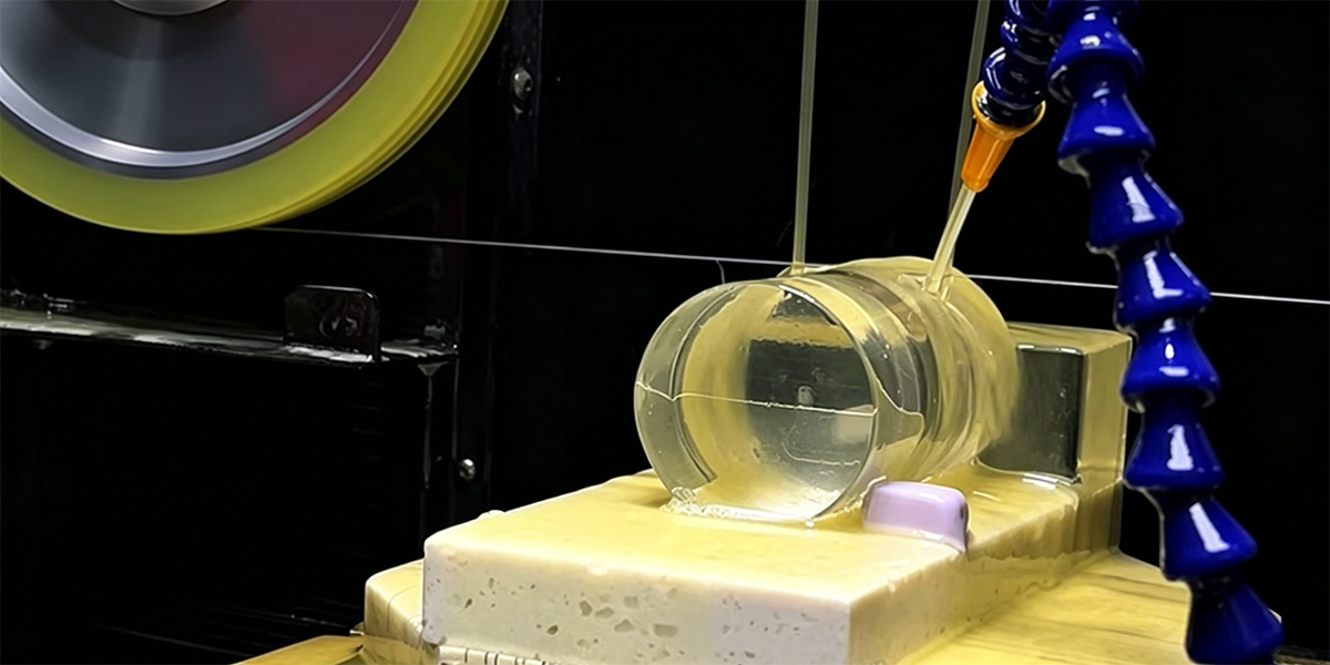
We utilize an Endless Diamond Wire Loop capable of linear speeds up to 60m/s. This high velocity, combined with a synchronized high-pressure cooling system, ensures a genuine “Cold Cutting” process.
-
The Technical Edge: By minimizing the contact time per abrasive grain, we prevent the aluminum matrix from reaching its plastic deformation temperature.
-
The Result: Complete elimination of “gumming” and Built-Up Edges (BUE). This preserves the material’s original temper and ensures the cutting zone remains structurally stable.
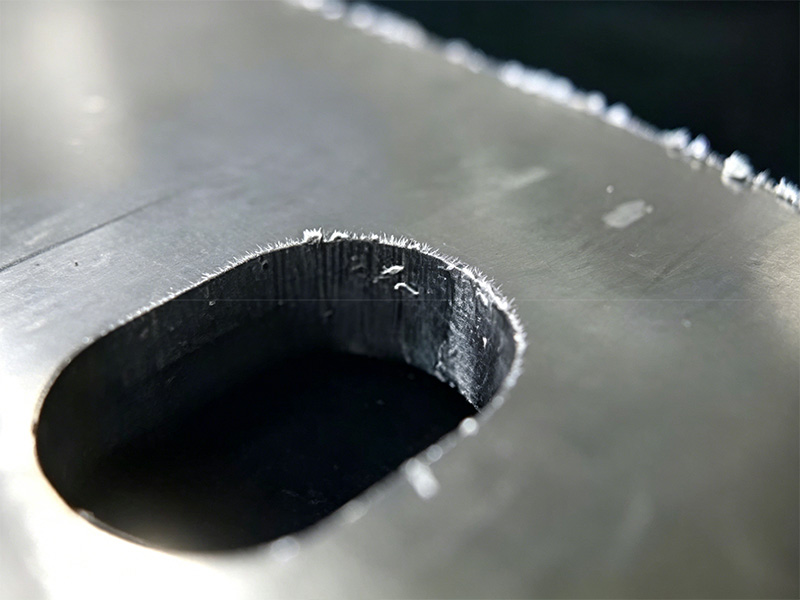
Traditional band saws or circular blades use teeth to rip through material, which inevitably “plucks” the hard silicon crystals out of the soft matrix. Zelatec’s diamond-impregnated wires act as thousands of microscopic grinding points.
-
The Technical Edge: Our wire slices directly through the silicon crystals rather than dislodging them.
-
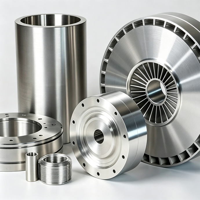
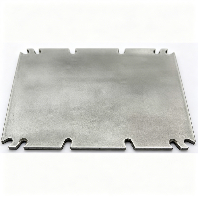
The Result: A flush, mirror-like surface (Ra<0.4 μm) with zero particle pull-out, no micro-cracking, and no subsurface damage, making it ideal for both industrial production and metallurgical SEM analysis.
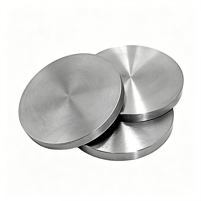
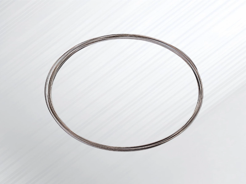
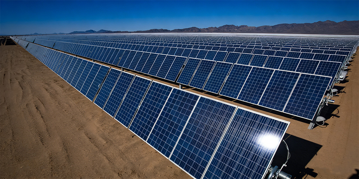
In high-volume production or when processing high-purity Al-Si targets, material loss is a direct hit to your bottom line. Our specialized wires are as thin as 0.3 mm – 0.5 mm.
-
The Technical Edge: We reduce the cutting path by up to 80% compared to traditional 2.0 mm thick blades.
-
The Result: You can recover up to 70% more usable material. For many clients, the reduction in raw material waste alone provides a full ROI (Return on Investment) within the first 12 months of operation.
A machine is only as good as its parameters. Our solution includes a consultative approach to ensure the equipment fits your specific alloy grade:
-
Segmented Wire Optimization: We select the specific diamond grit size and concentration that prevents aluminum chips from clogging the wire, ensuring long consumable life.
-
Customized Tension Control: Our proprietary tensioning system compensates for the vibration often found in metal cutting, ensuring the wire remains perfectly stable for a straight, vertical cut.
-
Advanced Filtration System: Because aluminum dust is light and abrasive, our solution features a multi-stage filtration system to keep the coolant clean and the cutting zone clear.
Diamond Wire Cutting: Where It Compares
At three points in the aluminum silicon alloy workflow, diamond wire changes the equation. Here is what to measure — and how it stacks up.
| Workflow Stage | Criteria | Conventional Tools & Their Performance | Diamond Wire Cutting |
|---|---|---|---|
| Point 1: Primary Sectioning & Billet Breakdown |
Kerf width | Band Saw / Circular Saw: 2–4 mm or wider | 0.3–0.5 mm — saves significant material |
| Surface quality | Burrs, tearing, silicon pull‑out | Smooth, no pull‑out, ready for next step | |
| Mechanical stress | Impact‑type cutting, micro‑crack risk | Low‑stress abrasive cutting, minimal crack risk | |
| Consumable life | Unpredictable, fast wear on silicon | Predictable, gradual wear by area cut | |
| Best fit | High‑volume rough cutting of standard castings | High‑value billets, aerospace/semiconductor grade — where material savings and part integrity matter | |
| Point 2: Precision Shaping & Near‑Net Cutting |
Effect on silicon particles |
CNC Milling: tool wear, particle pull‑out Wire EDM: recast layer, requires conductivity Laser Cutting: heat‑affected zone, micro‑cracks Waterjet: no heat, but wide, tapered kerf |
Cuts through particles cleanly, no pull‑out |
| Surface result |
CNC Milling: rough, needs stock removal Wire EDM: rough, needs post‑machining Laser Cutting: oxidized, molten residue Waterjet: grit contamination, rough |
Smooth, near‑finished surface | |
| Process stress |
CNC Milling: mechanical cutting force Wire EDM: thermal stress, altered surface layer Laser Cutting: severe thermal stress Waterjet: lower, but still impact erosion |
Minimal mechanical stress, cold cutting | |
| Material limitation |
CNC Milling: none Wire EDM: must be conductive Laser Cutting: reflectivity issues possible Waterjet: none |
None | |
| Kerf / material loss |
CNC Milling: tool diameter (mm) Wire EDM: 0.2–0.3 mm Laser Cutting: 0.1–0.3 mm Waterjet: 1–2 mm |
0.3–0.5 mm kerf | |
| Post‑processing |
CNC Milling: usually mandatory Wire EDM: must remove recast layer Laser Cutting: must remove HAZ Waterjet: often needs grinding & cleaning |
Often reduces or eliminates finishing | |
| Point 3: Sample & Test Coupon Preparation |
Thermal effect |
Abrasive Cut‑Off Wheel / Band Saw: dry cutting can burn, alter microstructure Wire EDM: recast layer and HAZ |
Wet, cold cutting — zero thermal effect |
| Mechanical damage |
Abrasive Cut‑Off Wheel / Band Saw: edge deformation, smearing, cracks Wire EDM: electrical erosion, surface alteration |
Low‑stress grinding, preserves true microstructure | |
| Precision |
Abrasive Cut‑Off Wheel / Band Saw: rough, poor positioning Wire EDM: high, but requires conductivity |
High, can produce complex shapes | |
| Result for analysis |
Abrasive Cut‑Off Wheel / Band Saw: high risk of false readings Wire EDM: recast layer interferes with edge analysis |
True representation of material condition |
What You Gain
Lower Kerf Loss
Ultra-thin 0.5 mm slicing minimizes waste and maximizes material saving.
Better Surface Finish
Achieve Ra < 0.4 μm directly from the cut, eliminating coarse grinding.
Reduced Micro-cracks
Low-stress slicing preserves integrity and avoids subsurface damage.
Less Post Polishing
Near-net shape results mean significantly reduced labor costs.
Higher Yield Rate
Increase your ratio of good parts, directly improving your profit.