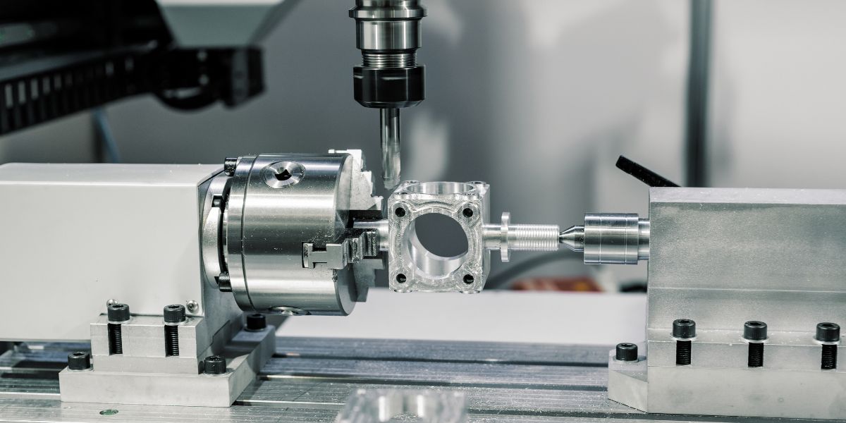
What Is CNC Milling?
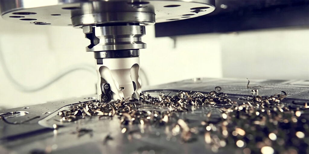
In one sentence: CNC milling is a subtractive manufacturing process that uses a computer-controlled rotating tool to carve precise parts from a solid block of material.
Think of it as a programmable rotary cutter. The tool spins at high speed and follows a digital toolpath, shaving off small chips of metal, plastic, or wood until the part takes shape. Because a computer program directs every move, the process is highly accurate and repeatable.
Process vs. machine — a simple distinction
People often use the terms interchangeably, but there is a practical difference:
- CNC milling → the process (the method of cutting under computer control)
- CNC milling machine → the physical equipment that performs the process
A quick way to remember it: milling is what you do; the machine is what you do it on.
CNC milling vs. manual milling
Manual and CNC milling both remove material with a rotating cutter. What changes is who (or what) is doing the guiding.
| Manual milling | CNC milling | |
| Control | Operator moves the table and tool by hand | Computer follows a written program (G-code) |
| Accuracy | Depends on operator skill | Repeatable within microns |
| Shape complexity | Limited by what can be done manually | Handles complex curves, pockets, and 3D surfaces |
| Production speed | Good for simple, one-off jobs | Runs unattended once set up; excellent for repeat jobs |
The bottom line: CNC milling can reliably produce shapes that are too difficult, too time-consuming, or simply impossible to make manually.
What is a CNC milling machine made of?
No matter the size or brand, almost every CNC milling machine has three core components:
- Spindle – the motorised unit that grips and spins the cutting tool. Spindle speed can range from a few thousand rpm for heavy metal removal to over 30,000 rpm for fine detail work.
- Worktable – the platform where the raw material is clamped. Depending on the machine design, either the table moves under the spindle or the spindle moves over the table. Secure workholding is essential to handle cutting forces.
- CNC control system – the “brain” that reads the program (G-code), coordinates movement along multiple axes, manages tool changes, and monitors the process.
Most machines move in at least three linear axes (X, Y, Z). Adding a 4th or 5th rotary axis allows angled features and complex geometries to be machined in a single setup.
One machine, multiple jobs
Not every CNC mill is built for just one kind of work. Some are designed purely for heavy cuts; others for delicate engraving. A growing number of machines — often described as engraving and milling machines — combine a high-speed spindle for fine detail with a rigid frame that can handle deep cuts and tougher materials. This kind of hybrid capability lets a shop run light surface engraving and heavy slot milling on the same platform, reducing setups and keeping process control tight.
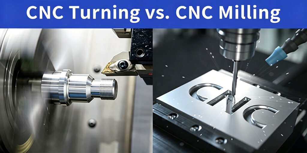
Milling vs. Turning vs. Engraving – What’s the Difference?
When you walk into a machine shop, three processes often get mixed up: milling, turning, and engraving. They all cut material, but the way the tool and the workpiece move is completely different.
| Process | How it works | Typical parts and features |
| Milling | A rotating tool moves around a stationary or slowly repositioned workpiece. | Flat faces, pockets, slots, complex 3D contours, mould cavities. |
| Turning | The workpiece spins at high speed while a stationary cutting tool removes material. | Shafts, pins, bushes, threads, and any round cylindrical parts. |
| Engraving | A small, sharp tool spins at very high speeds to trace fine lines or patterns on the surface. | Text, logos, serial numbers, decorative patterns, fine textures. |
In practice, engraving is often a fine-detail subset of milling. It uses similar machine kinematics — a rotating tool following a programmed path — but with much lighter cuts, higher spindle speeds, and smaller tools. The challenge is that a typical light-duty engraving machine may lack the rigidity for deep milling, and a heavy milling machine may not have the spindle speed for crisp engraving detail.
That’s why some machine builders now design rigid-frame machines that can do both. With a high-speed spindle, a stiff casting, and quality bearings, you can run fine engraving at 30,000 RPM and heavy slot milling in steel on the same platform. This combination reduces setups, saves floor space, and keeps process control under one roof — a practical choice for shops that need both surface detail and structural cutting capability.
How Does CNC Milling Work?
CNC milling turns a digital design into a physical part through a series of connected steps. Each step builds on the one before it, and skipping or rushing any of them usually shows up as a bad part later. Here is how the process flows in a typical shop.
At a glance: the 5-step workflow
- CAD design → 2. CAM programming → 3. Machine setup → 4. Automated cutting → 5. Part finishing
Step 1: CAD Design – Create the Digital Model
Everything starts with a 3D model. An engineer or designer uses CAD software (such as SolidWorks, Fusion 360, or NX) to build a detailed digital version of the part. The model includes all the geometry — holes, pockets, curves, threads — and defines the nominal dimensions and tolerances.
At this stage, no cutting has happened yet. But decisions made here — wall thickness, corner radii, hole depths — directly affect how easy or difficult the part will be to machine later.
Step 2: CAM Programming – From Model to Toolpath
Once the CAD model is ready, it moves into CAM software (Computer-Aided Manufacturing). This is where the machining strategy gets defined.
The programmer or machinist chooses:
- Which cutting tools to use
- The order of operations (roughing first, then finishing)
- How the tool will approach the material — the toolpath
- Cutting parameters: spindle speed, feed rate, depth of cut
The CAM software then generates a set of instructions in G-code, the programming language that CNC machines understand. Think of G-code as a detailed script: move here, plunge this deep, cut along this path at this speed, retract, change tool, repeat.
Step 3: Machine Setup – Prepare the Physical Workspace
Before any chips fly, the machine needs to be set up correctly. This is a hands-on step that makes a real difference in part quality.
Setup involves:
- Clamping the raw material (the workpiece) securely on the worktable — using a vice, clamps, or a custom fixture
- Loading the required cutting tools into the spindle or the automatic tool changer magazine
- Setting the work coordinate system — telling the machine where the part sits in space by touching off tools to the workpiece and defining the zero point
A sloppy setup will produce a sloppy part, no matter how good the program is. That’s why experienced machinists treat this step seriously.
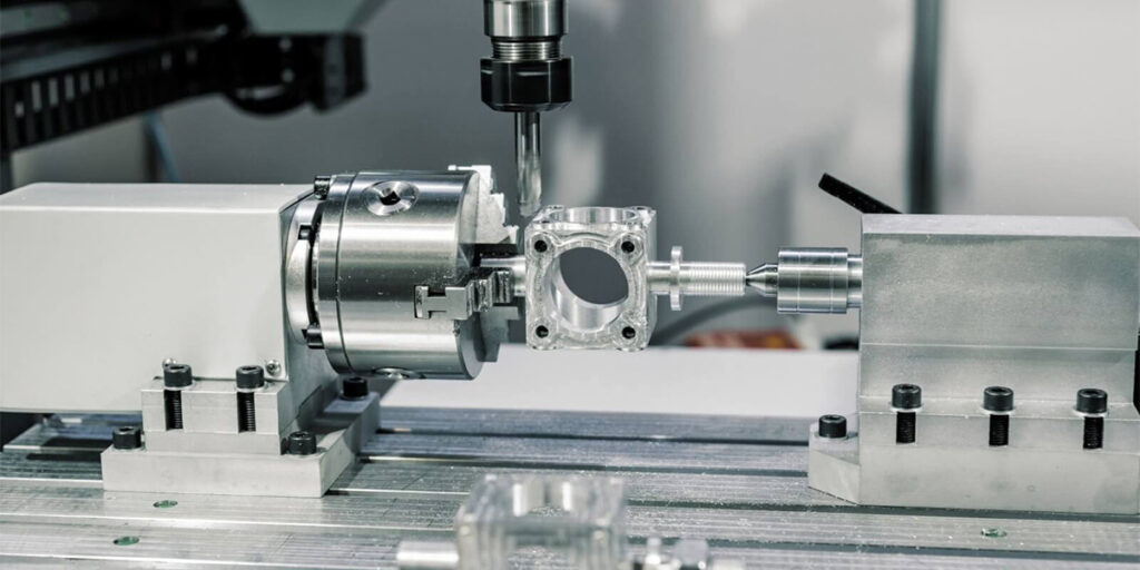
Step 4: Automated Cutting – The Machine Takes Over

Once the program is loaded and the setup is checked, the operator presses cycle start. From here, the CNC control system takes over.
The spindle spins the cutting tool at the programmed speed. The machine moves the tool along the toolpath, either by moving the tool, the table, or both, depending on the machine design. Material is removed in small chips, layer by layer. The control system coordinates multiple axes simultaneously, maintains the programmed feed rate, and can automatically swap tools from the magazine when needed.
For complex parts, a single cycle might involve several different tools — a face mill to flatten the top, a large end mill to rough out the main cavity, a smaller end mill to finish the details, and a ball nose cutter to create smooth 3D surfaces. The machine handles the sequence without operator intervention.
Step 5: Part Finishing – After the Spindle Stops
When the cycle finishes, the nearly complete part comes off the machine. But the job is not done yet.
Typical post-machining steps include:
- Removing the part from the fixture
- Deburring — cleaning up sharp edges and small burrs left by cutting
- Cleaning — removing coolant, chips, and oil
- Inspection — checking critical dimensions with callipers, micrometres, or a CMM (coordinate measuring machine) to verify the part matches the drawing
For many shops, this final inspection is the step that confirms whether the earlier CAD, CAM, and setup work was done correctly. If a dimension is off, the process gets adjusted and the next part comes out right.
Types of CNC Milling Machines: Which One Fits Your Project?
CNC milling machines are not “one-size-fits-all.” They are categorized based on their movement (axes), their orientation, and their specific industrial purpose. Choosing the right type is essential for balancing part complexity with production costs.
1. Classification by Axes: From Simple to Complex
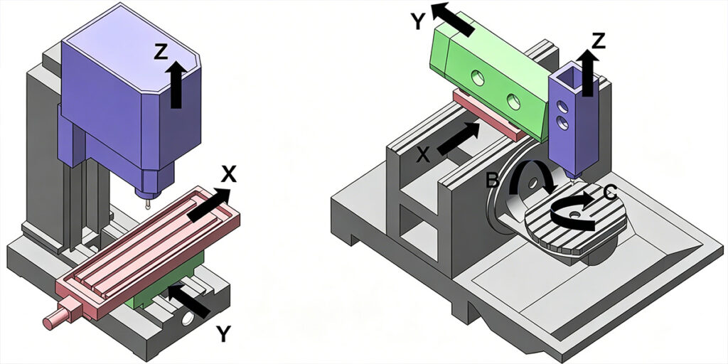
The number of axes determines a machine’s ability to handle intricate geometries and the number of setups required.
- 3-Axis CNC Milling: The most common “workhorse.” The tool moves along the X, Y, and Z axes. It is ideal for flat parts or features that exist on a single plane. While highly cost-effective, complex parts may require manual repositioning.
- 4-Axis CNC Milling: This adds a rotation axis (A-axis) to the table. It allows the machine to rotate the workpiece, making it perfect for cutting slots or holes around the side of a cylinder without stopping the machine.
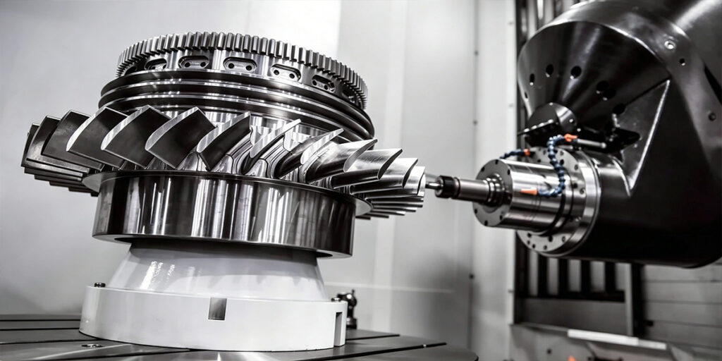
- 5-Axis CNC Milling: The pinnacle of precision. With two additional rotation axes, the tool can reach almost any angle. This is used for aerospace turbine blades or complex medical implants. Its main advantage is “one-and-done” machining—completing a complex part in a single setup, which drastically increases accuracy.
Quick comparison by axes
| Axis | Setup flexibility | Complex surfaces | Relative cost | Typical parts |
| 3 | Low – one main face per setup | No | Low | Plates, housings, brackets |
| 4 | Medium – adds side features | No | Medium | Shafts, manifolds, side‑ported parts |
| 5 | High – any face, any angle | Yes | High | Blades, impellers, organic shapes |
2. Vertical vs. Horizontal Machining Centers
The orientation of the spindle dictates how the machine handles material and waste (chips).
- Vertical Machining Centers (VMC): The spindle is vertical. These are popular for their ease of setup, lower cost, and high visibility for the operator. They are excellent for detailed work on flat plates.
- Horizontal Machining Centers (HMC): The spindle is horizontal. These are built for high-volume industrial production. Because of the orientation, chip evacuation is superior—gravity pulls the metal chips away from the tool, preventing recutting and extending tool life.
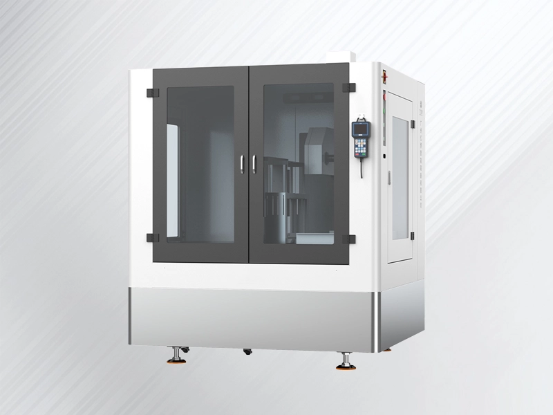
3. Portal and Gantry Milling Machines
When projects scale up, so does the machine. Gantry mills feature a bridge-like structure moving over a large stationary table. These are indispensable for machining large-format industrial components, such as oversized aluminum extrusions or structural aircraft parts, where stability over a long distance is critical.
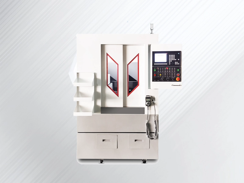
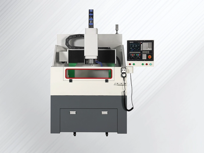
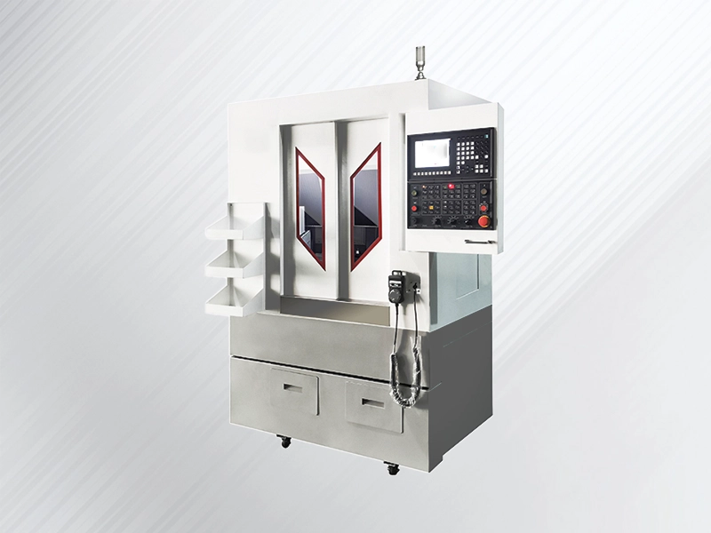
4. Specialized Hybrid: Engraving and Milling Machines
For businesses that require both high precision and delicate finishing, a CNC Engraving and Milling Machine offers a versatile middle ground. These machines combine high spindle speeds (often 24,000 RPM or higher) with the rigidity of a mill. This allows you to perform heavy-duty milling on aluminum and then immediately switch to fine engraving for serial numbers or logos—providing a multi-functional solution that saves floor space and investment costs.
Types of Milling Operations
A CNC milling machine can perform a wide range of cutting operations, each defined by the tool used and the path it follows. Below are the most common milling operations found in modern shops. For each one, you’ll find a concise definition and a typical practical use.
Types of Milling Operations
| Operation | What it is | Typical use |
| Face Milling | The cutter’s end face removes a thin layer from the top surface of the workpiece. | Creating a flat, smooth reference surface as a first operation or bringing a part to final thickness. |
| Plain Milling (Slab Milling) | A cutter with teeth on its periphery moves parallel to the workpiece surface, removing material along a broad, flat plane. | Roughing down a large flat surface quickly before finishing with face milling. |
| Side Milling | Cutting is done primarily by the teeth on the side of the cutter, producing a vertical surface perpendicular to the tool axis. | Squaring up a block or machining a precise vertical wall. |
| Slot Milling | The cutter plunges into the material or traverses sideways to create a narrow groove or slot. | Cutting keyways, T-slots, or any long recess with parallel side walls. |
| End Milling | A general-purpose operation using the end and the periphery of an end mill to cut pockets, shoulders, and profiles. | Machining internal cavities, contouring edges, or finishing surfaces in tight corners. |
| Shoulder Milling | A side-milling variation that produces both a vertical face and a horizontal ledge in one pass, creating a stepped edge. | Making locating shoulders, flange faces, or mating surfaces that must seat flush against another part. |
| Profile Milling | The tool follows an irregular or curved outer contour of the part, either on the outside or along an internal wall. | Shaping complex external outlines of brackets, cams, or mould cavities with smooth curves. |
| Pocket Milling | An end-milling operation that clears out a closed area inside a part, moving back and forth in layers to remove all material within the boundary. | Creating recessed areas, weight-reduction pockets, or cavities for electronic housings. |
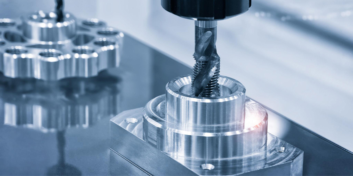
| Thread Milling | A rotating cutter moves in a helical path to cut internal or external threads, without using a conventional tap or die. | Producing threads in difficult-to-machine materials, large diameters, or where fine control over thread fit is critical. |
| Gear Milling | A formed cutter, shaped to the exact tooth profile, cuts each gear tooth space one after the other. | Manufacturing spur gears, helical gears, or splines on standard CNC mills instead of dedicated gear-making machines. |
| Angle Milling | The cutter or the workpiece is tilted at a defined angle to produce a sloped surface, chamfer, or bevel. | Cutting chamfered edges, dovetail grooves, or angled seating surfaces on fixtures. |
| Form Milling | A custom-ground cutter with a specific cross-section shape reproduces that shape directly into the workpiece in one pass. | Creating repeated special profiles, such as moulding shapes, concave radii, or irregular grooves that standard cutters can’t produce. |
| Straddle Milling | Two cutters mounted on the same arbor machine two parallel surfaces at the same time. | Squaring up both sides of a rectangular block in one setup, or producing a precise hexagonal or square end profile. |
| Helical Milling | The tool moves along a helical path — a combination of circular and linear motion — to generate a cylindrical or conical feature with a curved profile. | Machining helical grooves, screw compressor rotors, or large-diameter bore contouring without a large end mill. |
| T-Slot Milling | A specialty slot-milling operation where a T-shaped cutter first cuts a standard slot and then widens the bottom to create a T-shaped recess. | Producing machine table T-slots for clamping fixtures. |
All of these operations share the same basic principle: a rotating tool moving through material along a precisely controlled path. The only difference lies in the cutter shape and the toolpath strategy. A well‑rounded CNC programmer will mix and match several of these in a single part program — face milling the top, roughing a pocket with end milling, finishing the side walls with a profiling pass, and then thread milling the bolt holes. Understanding what each operation does helps designers create parts that can be machined efficiently with as few setups as possible.
Workpiece Materials & Cutting Tools
The materials you put on the table and the tools you load into the spindle decide most of the machining result. Below is a practical overview of what gets cut and what cuts it.
Materials at a glance
| Material | Machinability | Typical parts |
| Aluminium (6061, 7075) | Excellent – high speeds, good finish | Housings, brackets, aerospace plates |
| Mild steel (1018, A36) | Good – predictable cut, moderate tool wear | Shafts, frames, general components |
| Alloy steel (4140, 4340) | Fair – tougher, needs rigid setup | Gears, axles, high‑strength parts |
| Stainless steel (304, 316) | Moderate – work‑hardens, needs sharp tools | Food equipment, medical, marine parts |
| Tool steel (D2, H13, P20) | Difficult – abrasive, pre‑hardened options | Moulds, dies, punches |
| Titanium (Ti‑6Al‑4V) | Difficult – heat concentrates at tool tip | Aerospace, implants, performance parts |
| Cast iron | Good – short chips, but abrasive dust | Machine beds, engine blocks, brake parts |
| Brass, bronze | Excellent – smooth finish, low tool wear | Valves, bearings, fittings |
| Copper | Fair – gummy, needs sharp polished edges | Electrical contacts, heat sinks |
| Plastics (nylon, acetal, acrylic, PTFE, PEEK) | Excellent (with sharp tools) – watch for melting | Prototypes, insulators, seals, bushings |
| Ceramics, glass | Very difficult – diamond tools, light cuts | Semiconductor, optical, wear parts |
| Magnesium alloys | Excellent – but chip fire risk needs care | Lightweight housings, aerospace |
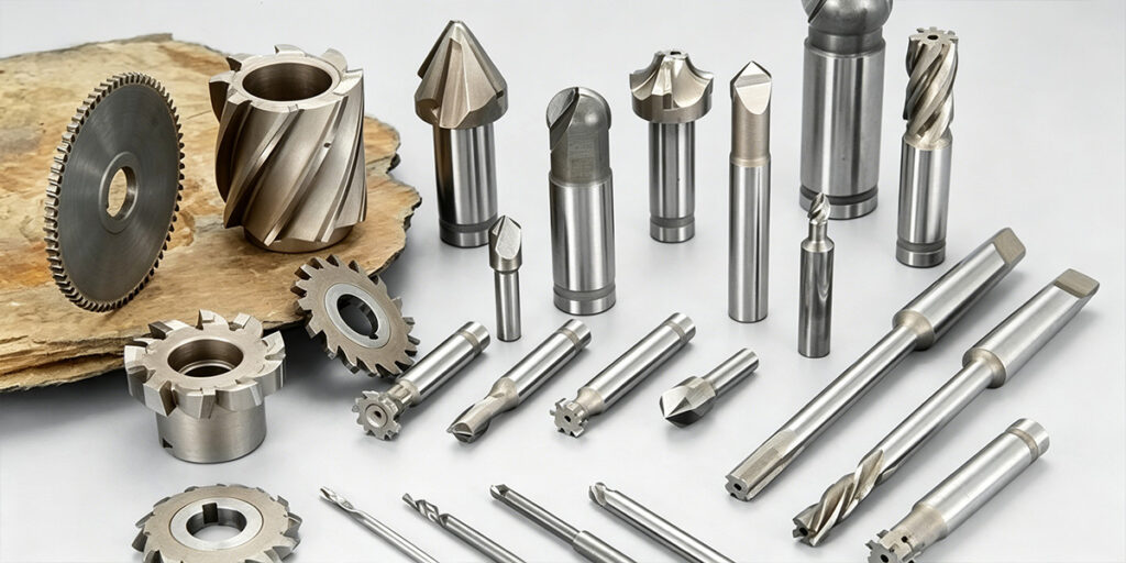
Common cutting tools
- End mills – The everyday cutter. Comes in square‑end, corner‑radius, and ball‑nose. Solid carbide with TiAlN or AlTiN coatings handles most steels and aluminium at high speeds. High‑speed steel (HSS) is still used for low‑volume or softer materials.
- Ball nose cutters – End mills with a round tip for 3D contouring and smooth surface finishing on mould cavities and curved parts.
- Face mills – Large‑diameter cutters with multiple carbide inserts. Built to flatten big surfaces fast and create a flat reference face.
- Slot drills – Two‑flute cutters that can plunge straight down into the material. Made for keyways, slots, and closed pockets.
- Thread mills – Single‑point or multi‑form tools that follow a helical path to cut internal or external threads. One tool can cover many diameters with the same pitch.
- Chamfer mills and angle cutters – Create consistent bevels, deburr edges, or machine angled profiles like dovetails.
- Form cutters and gear cutters – Custom‑profile tools that reproduce a specific shape in one pass, such as gear tooth spaces or decorative moulding profiles.
- Drills and reamers – Run in the same spindle. Drills make holes; reamers bring them to exact diameter and finish.
Pro Tip: To get the most out of advanced carbide tools, you need a machine with high structural rigidity (such as those using HT300 cast iron frames). High-rigidity prevents micro-vibrations that cause carbide tools to chip, allowing you to run at higher spindle speeds and achieve a mirror-like surface finish.
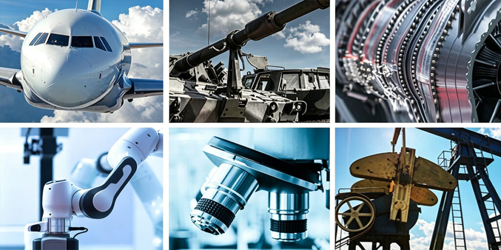
Real-World Applications: Where Is CNC Milling Used?
CNC milling is the backbone of modern manufacturing. Because it can handle a wide variety of materials with micron-level precision, it is utilized across almost every high-stakes industry. If a part requires high structural integrity and complex geometry, it was likely created on a CNC mill.
Key Industries and Typical Components
- Automotive Industry:
- Examples: Engine blocks, cylinder heads, gearbox housings, and custom brake components.
- Value: CNC milling ensures these parts can withstand high heat and mechanical stress with perfect fitment.
- Aerospace & Defense:
- Examples: Turbine blades, wing spars, landing gear components, and fuel manifold parts.
- Value: Often requiring 5-axis machining and exotic materials like Titanium, this industry relies on milling for its “zero-failure” tolerance.
- Medical Devices:
- Examples: Orthopedic implants (hips/knees), surgical instruments, and housings for MRI machines.
- Value: Biocompatible materials like Stainless Steel 316L and Titanium are easily processed to meet strict FDA-level surface finish requirements.
- Consumer Electronics:
- Examples: Smartphone frames, laptop enclosures, and heat sinks.
- Value: High-speed milling centers allow for the mass production of aesthetic, lightweight, and durable aluminum bodies.
- Mold & Die Making:
- Examples: Injection molds, die-casting dies, and forging tools.
- Value: Milling is essential for creating the incredibly precise cavities and cores used to mass-produce plastic and metal consumer goods.
- Industrial Automation:
- Examples: Precision jigs, fixtures, robotic arm joints, and sensor housings.
- Value: Custom tooling allows factories to automate their own production lines with high repeatability.
Why These Industries Choose CNC Milling
Beyond just “making parts,” CNC milling offers scalability. Whether a company needs a single prototype for a new medical tool or 10,000 units of an automotive bracket, the process remains consistent. For B2B buyers, this means lower long-term costs and a faster time-to-market for critical industrial components.
Advantages and Limitations of CNC Milling
Every manufacturing process has things it does well and things it doesn’t. Knowing both sides helps you use CNC milling where it truly adds value.
Advantages
High precision
A properly maintained CNC mill can hold tolerances within a few microns. The machine follows programmed coordinates, removing the small inconsistencies that come with manual operation. This level of control is essential for parts that must fit together perfectly — bearing seats, seal surfaces, and locating features.
Repeatability
Once a program is proven, you can run one part or a thousand and get essentially the same result. This consistency means you can trust the process for production batches, spare parts made months apart, or replacement components that need to match existing assemblies.
Complex geometry capability
CNC milling can produce shapes that would be very difficult or impossible by hand — 3D contoured surfaces, deep pockets, undercuts, and intricate profiles. Multi-axis machines can reach several faces of a part in one setup, reducing the number of times the workpiece needs to be moved and re-clamped.
Efficiency and automation
A CNC machine can run unattended after setup, including overnight or over weekends. Automatic tool changers switch cutters without stopping the spindle, and pallet systems can load the next workpiece while the current one is being cut. This keeps the machine productive for more hours in the day.
Broad material compatibility
With the right tooling and cutting parameters, the same CNC mill can work with aluminium, carbon steel, stainless steel, titanium, engineering plastics, and even advanced ceramics. This flexibility allows a single machine to support prototyping, job shop work, and mixed-material production.
Low-volume flexibility
Because it doesn’t need dedicated tooling like moulds or stamping dies, CNC milling is practical for one-off parts, small batches, and custom projects. You can go from a CAD model to a finished part without waiting for special tooling to be made.
Limitations
High initial investment
Industrial-grade CNC machines, together with tooling, CAM software, and skilled operator training, represent a significant upfront cost. For businesses with low or irregular workloads, the return on that investment can take time.
Ongoing tooling costs
Cutting tools wear with use, especially in abrasive or tough materials. Keeping tooling in good condition requires regular inspection and replacement. High-speed cutting and hard workpiece materials can accelerate tool consumption.
Material and geometry constraints
Some materials are simply tough to machine. Hardened tool steels, titanium alloys, and nickel-based superalloys demand rigid machines, careful speed selection, and high-quality tool coatings. Certain shapes — very deep narrow slots, sharp internal corners, and extremely thin walls — are hard to produce with a round rotating tool, regardless of the machine’s accuracy.
Work envelope limits
Every milling machine has a defined working volume. Parts that exceed the table travel in any direction must either be machined in multiple setups (which risks losing alignment) or moved to a larger machine. Very large parts like structural weldments or big mould bases often require specialised gantry or portal machines.
Programming and skill requirements
Effective CNC milling isn’t just loading a file and pressing start. It requires someone who can choose the right cutting strategy, set feeds and speeds accurately, design secure workholding, and troubleshoot when surface finish or dimensions start to drift. Finding and keeping that expertise remains a real challenge in many markets.
Not always the fastest or cheapest option
For simple round parts, turning is usually quicker and more economical. For very high volumes of simple shapes, stamping or die casting can produce parts at a much lower cost per unit once the initial tooling investment is covered.
CNC milling works best when part complexity, precision, and flexibility matter more than squeezing out the absolute lowest unit cost. Understanding where the process fits — and where it doesn’t — keeps shops from misapplying a powerful but specific manufacturing tool.
Design Considerations for CNC Milling
Designing parts for CNC milling is about working with the process rather than fighting it. A few practical rules keep machining time down, tooling simple, and tolerances achievable.
Internal corner radii
A rotating round cutter cannot leave a sharp internal corner. The minimum inside radius should be at least half the cutter diameter. A common rule is to use the largest radius the part function allows — this reduces tool changes and lets larger, stiffer cutters work faster. For a typical general-purpose end mill, a 3–5 mm internal radius is comfortable; smaller radii demand smaller tools and higher cost.
Wall thickness
Very thin walls vibrate under cutting forces and can deflect or break. For aluminium, keep unsupported walls above 0.8–1.0 mm; for steel, stay above 1.5 mm. Tall, thin features need even more thickness or must be supported with fixturing. A rigid machine helps, but the geometry sets the limit.
Hole depth and diameter
Deep, narrow holes are difficult to machine. A practical guideline: keep hole depth no more than 4–5 times the diameter for standard drilling. Beyond that, chip evacuation and tool wandering become real problems. For threaded holes, thread milling can reach deeper than taps with better control.
Tool accessibility
The cutter has to physically reach every surface to be machined. Features hidden behind walls or in deep pockets may need extended-reach toolholders or become unmachinable from that direction. Designers should imagine a cylinder representing the tool and check whether it can access each feature without the holder colliding with the part.
Tolerances
Specify tight tolerances only on functional surfaces — bearing seats, alignment features, mating faces. Over-tolerancing drives up cost without improving part performance. A general tolerance of ±0.1 mm is easy to hold; ±0.01 mm requires careful setup, sharp tools, and a rigid machine.
Text and surface detail
When adding lettering or logos, raised (embossed) text machines faster than engraved (recessed) text because less material must be removed. Engraved text looks crisp but takes longer. For both, choose simple sans-serif fonts and keep the depth shallow. A high-speed spindle combined with a rigid machine structure allows fine detail and smooth surface finishes without chatter, even on larger parts.
Cost of CNC Milling
CNC milling costs break down into two main areas: the machine purchase and the per‑part machining cost. Understanding both helps you budget realistically.
Machine cost range
A basic desktop CNC router can start under $1,000. A capable 3‑axis vertical machining centre for professional use typically ranges from $30,000 to $100,000. Larger, multi‑axis machines or those with pallet changers and advanced controls easily reach $150,000 and above. Tooling, workholding, CAM software, and setup add to the initial outlay.
Factors that drive per‑part machining cost
- Material – Stock material choice affects both raw material price and how fast it can be cut. Aluminium is cheaper to machine than titanium or hardened steel.
- Complexity – Parts with many features, tight tolerances, or deep cavities need longer programming, more setups, and smaller tools, all of which increase time and cost.
- Machine time – The biggest variable. Every minute the spindle runs adds cost. Designers can reduce this by keeping features accessible from one side and using standard tooling.
- Tool wear – Hard, abrasive, or tough materials consume cutting tools more quickly. Frequent tool changes and shorter tool life raise the cost per part.
- Batch size – One‑off parts carry the full setup cost. Larger batches spread setup, programming, and fixturing costs across many parts, lowering unit price significantly.
In practice, the most effective way to control CNC milling cost is to design parts with the process in mind and to match the batch size to the project’s real needs.
Finding the Right Solution for Your Project
CNC milling is more than just a cutting process; it is a vital technology that empowers modern industry to achieve unprecedented precision and scalability. Whether you are producing complex aerospace components or high-end industrial aluminum profiles, selecting the right machinery is the first step toward manufacturing excellence.
At Zelatec, we specialize in bridging the gap between heavy-duty milling and high-precision detailing. Our Engraving and Milling Machines are engineered with high-rigidity frames to handle diverse materials while maintaining the delicate touch required for fine finishes.
Ready to optimize your production line? Contact our engineering team today for a technical consultation or a custom quote. Let’s discuss how Zelatec’s solutions can bring your designs to life with unmatched accuracy.