What Is Wire Cutting?
In the world of high-precision manufacturing, wire cutting is much more than a simple “cutting method.” Formally, it is a high-accuracy fabrication process characterized by material removal by abrasive wire motion. Instead of applying brute mechanical force like a traditional blade, wire cutting relies on the continuous movement of a thin, specialized wire to perform precise abrasive slicing.
In modern industrial applications, “wire cutting” typically refers to two distinct technologies, each serving a specific purpose:
- Wire EDM (Electrical Discharge Machining): This is an electro-thermal process used for conductive materials. It utilizes a continuous thin metal wire as an electrode, removing material through controlled, rapid-fire pulse sparks. It is the go-to for complex shapes in hardened steels.
- Diamond Wire Cutting: Unlike traditional methods that may use loose abrasive slurries, modern diamond wire saws feature wire impregnated with diamond micro-particles. This is a “cold cutting” technique that removes material via physical grinding. It is the industry standard for slicing non-conductive, brittle, or high-value materials like silicon, sapphire, and advanced ceramics.

Why Is Wire Cutting Critical?
The importance of wire cutting lies in its ability to handle materials that are too hard or too fragile for conventional machining. Because the wire is incredibly thin, it ensures minimal kerf loss (material wasted during the cut), which is vital when processing expensive materials.
Furthermore, because it exerts low mechanical stress on the workpiece, it prevents cracking and maintains the structural integrity of the material. Whether you are slicing semiconductor wafers or dicing industrial magnets, wire cutting provides the surface finish and geometric precision that traditional sawing simply cannot match.
Principle of Wire Cutting
To understand industrial wire cutting, it is helpful to set aside the image of a toothed blade forcing its way through material. Instead, modern precision wire cutting operates on either controlled micro-abrasion or pulsed electrical vaporization. While the outcomes appear similar—a narrow slit in a hard workpiece—the underlying cutting mechanism for Diamond Wire Cutting and Wire EDM could not be more distinct. Understanding this distinction is essential for selecting the correct process and achieving reliable precision control.
1. Diamond Wire Cutting: Mechanical Abrasion (Fixed Abrasive Method)
Diamond Wire Cutting is fundamentally a fixed abrasive machining process. The cutting tool is an abrasive wire—a high-tensile steel core electroplated with industrial diamond grit. Unlike older “loose abrasive slurry” systems where abrasive grains roll freely, here the diamonds are rigidly bonded to the wire surface.
The cutting action is governed by three interdependent process variables:
- Wire Speed: In closed-loop diamond wire systems, wire speed typically ranges from 4 mm/min to 8 mm/min. High velocity ensures that each diamond particle engages the workpiece with fresh, unworn cutting edges continuously. The rapid pass-through prevents localized heat buildup and maintains consistent material removal rates. Faster is not always better—speed must be balanced with material hardness to avoid excess wire wear and erratic cutting behavior.
- Wire Tension: Precise tensioning (often 40 N to 80 N depending on wire diameter) maintains the abrasive wire in a taught, linear path. Insufficient tension permits the wire to wander laterally, producing wavy cut faces and poor geometric tolerance. Excessive tension risks premature wire breakage, interrupting production and scrapping the workpiece. Modern diamond wire machines employ closed-loop tension control to keep the wire rigid within microns of ideal position.
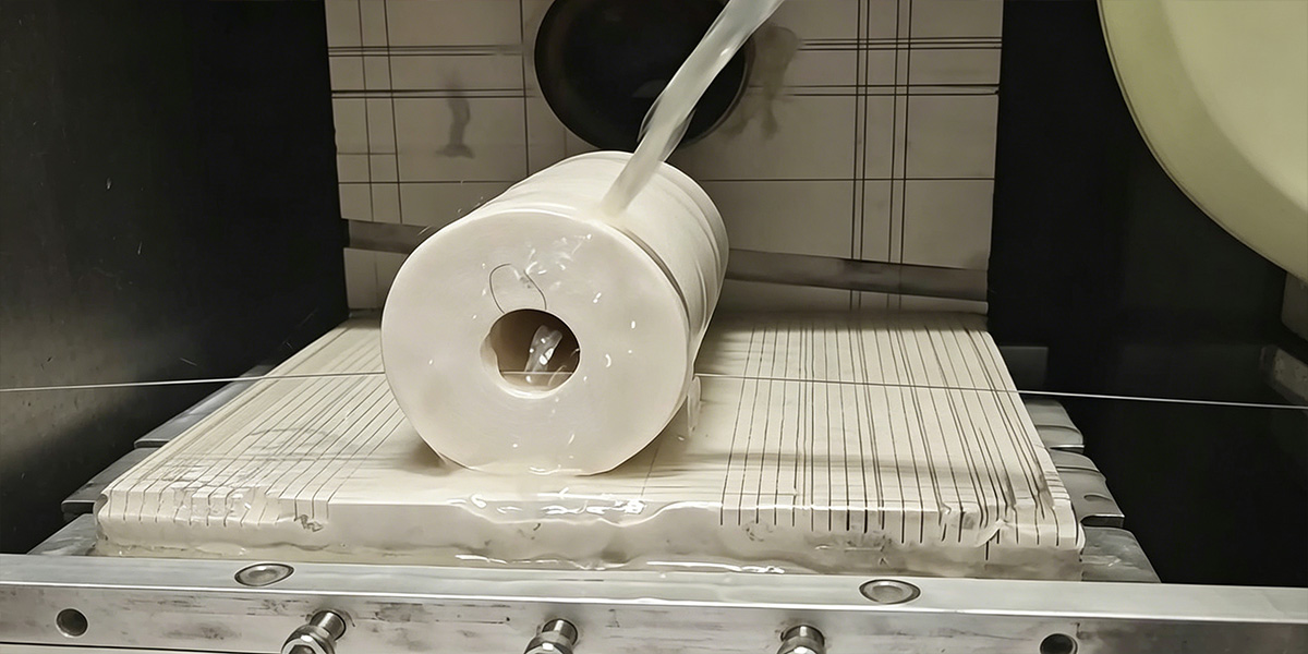
- Coolant Delivery: A continuous stream of water-based coolant is directed at the cutting zone. This fluid serves three functions: it lubricates the diamond–workpiece interface, carries away the microscopic swarf (grinding debris), and most critically, maintains a stable cold cutting thermal environment.
The material removal happens at the micro-scale. Each exposed diamond tip acts as an individual cutting point, plowing a shallow groove in the workpiece surface. As millions of these abrasive points pass through the material per second, a clean kerf is formed. The width of this groove is termed kerf loss—the portion of material permanently converted to dust and lost to the process. For modern diamond wire saws, kerf loss can be held as narrow as 0.10 mm to 0.30 mm, a critical economic factor when slicing expensive monocrystalline boules of silicon carbide (SiC) or sapphire.
Because the grinding interface generates minimal heat—and because the coolant immediately evacuates what little heat is produced—this is definitively a cold cutting method. There is no heat-affected zone (HAZ) to alter microstructural properties, meaning sintered magnets remain magnetic and semiconductor substrates retain their precisely engineered crystal orientation.
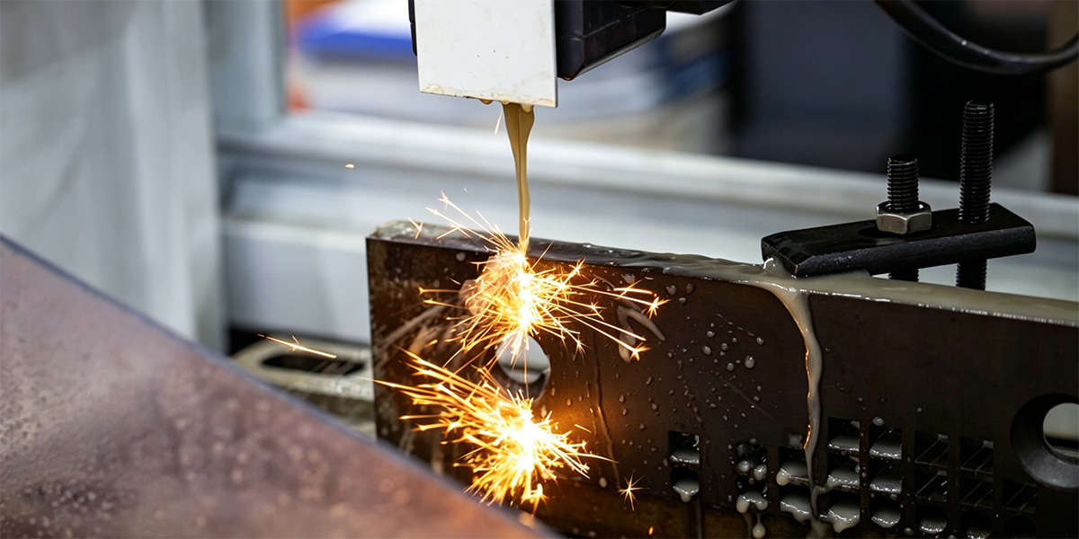
2. Wire EDM: Thermo-Electric Erosion (Spark Erosion Method)
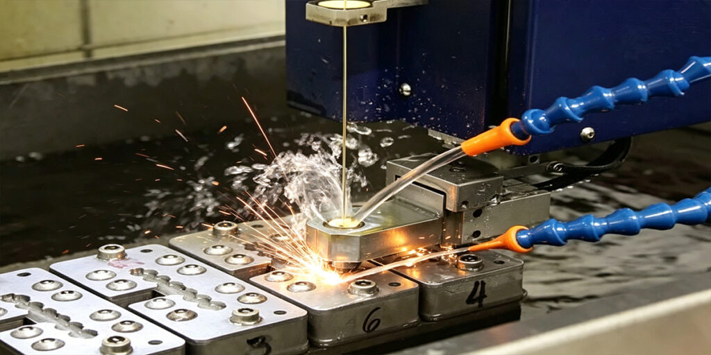
Wire EDM replaces mechanical abrasion with controlled electrical discharge. The wire here is not an abrasive; it is a conductive electrode—typically brass, zinc-coated copper, or tungsten—that never makes physical contact with the workpiece. A precise micro-gap (typically 0.025 mm to 0.050 mm) is maintained between the moving wire and the conductive workpiece, continuously monitored and adjusted by the machine’s servo system.
The cutting mechanism relies on rapid, sequenced electrical pulses. When voltage is applied, the dielectric fluid in the spark gap ionizes, creating a narrow plasma channel. A spark discharges across this gap, generating localized thermal energy between 8,000°C and 12,000°C. This extreme heat instantly melts and partially vaporizes a microscopic volume of workpiece material. The surrounding dielectric fluid then rapidly quenches the spark channel, collapsing the plasma and flushing the eroded particles away.
Crucially, Wire EDM is only effective on electrically conductive materials. Non-conductors—such as technical ceramics, glass, or bonded magnets—cannot support the spark mechanism; attempting to cut them results in nothing but a stopped machine and a broken wire.
Precision Control and Kerf Considerations
Both methods demand rigorous precision control, though the control variables differ:
- Diamond Wire Cutting requires precise monitoring of wire speed, feed pressure, tension, and coolant flow. Fluctuations in any of these degrade surface finish and geometric accuracy. The kerf loss is a direct function of wire diameter plus the diamond protrusion height.
- Wire EDM requires precise management of pulse duration (on-time), peak current, wire feed rate, and spark gap voltage. Kerf width equals wire diameter plus the overburn (twice the spark gap). While EDM can achieve exceptionally tight tolerances, it is inherently a thermal process; a thin recast layer always forms on the cut surface, which may require post-processing in high-reliability applications.
Diamond Wire Cutting(FLA) vs. Wire EDM
When specifying a cutting process, the choice between Diamond Wire and Wire EDM determines material compatibility, throughput, and part quality. The table below summarizes the practical distinctions.
| Dimension | Diamond Wire Cutting | Wire EDM |
| Mechanism | Physical grinding via fixed diamond abrasive | Spark erosion via electrical discharge |
| Thermal Impact | Cold cutting – negligible heat, no HAZ | Extreme localized heat, recast layer present |
| Material Range | Nearly all hard/brittle solids (conductive/non-conductive) | Conductive materials only |
| Shape Capability | Excellent for straight cuts and gentle contours | Superior for intricate internal geometries |
| Speed & Throughput | High wire speed (up to 80 m/s), fast sectioning | Typically slower, pacing limited by spark gap |
| Surface Finish | Smooth as-cut, minimal post-processing | May require secondary polishing to remove recast |
| Kerf Loss | Determined by wire diameter; as low as 0.10–0.30 mm | Wire diameter plus spark gap; similar range |
Practical Takeaway: Use Diamond Wire Cutting when material integrity and zero thermal alteration are non-negotiable. Choose Wire EDM only when the workpiece is conductive and extreme shape complexity outweighs the need for a pristine surface.
Types of Wire Cutting Technology
Wire cutting is not a one-size-fits-all process. Different technologies have evolved to meet specific manufacturing demands, from high-volume semiconductor wafering to precision tool and die making. The choice of technology often comes down to the material being cut, the required precision, and production economics. Below are the four primary categories you will encounter in industrial settings.
Reciprocating Wire Cutting
Reciprocating wire cutting is widely used in wire EDM (electrical discharge machining), primarily for cutting conductive materials such as hardened tool steels, carbide, and titanium. In this method, a thin metallic wire electrode — typically molybdenum or brass — moves back and forth at high speed, generating electrical sparks that erode the workpiece. Among its subtypes, “fast wire” offers high cutting speed but moderate accuracy (roughly ±0.01–0.02mm), making it suitable for roughing operations like stamping die blanks. “Slow wire,” by contrast, uses a single-pass copper electrode moving at low speed, delivering exceptional precision (±0.001mm) for intricate aerospace and medical components, though at significantly higher operating cost.
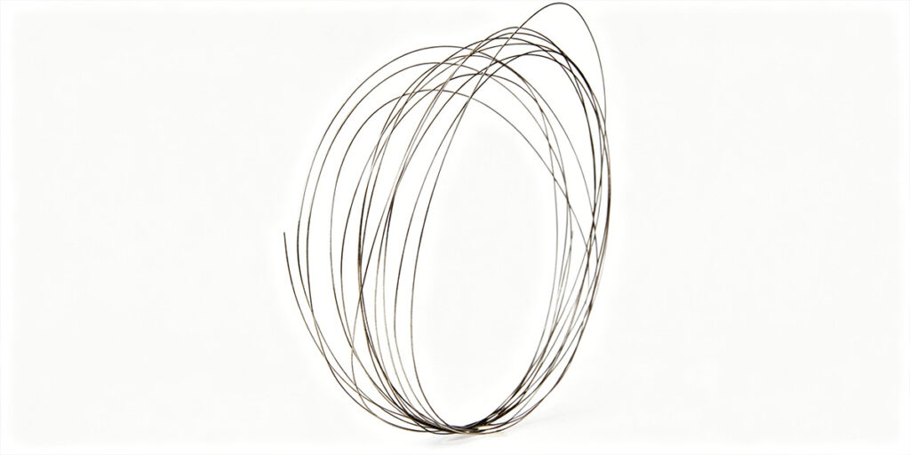
Endless Wire Loop Cutting
Endless wire loop cutting, also known as closed-loop or continuous diamond wire sawing, employs a seamless loop of high-strength steel wire electroplated with diamond abrasives. The wire runs in a single direction at high linear speeds (up to 50 m/s) without the need to reverse or re-spool. This continuous motion produces a narrow kerf and minimal material loss. The technology is highly versatile, capable of cutting a broad range of hard and brittle materials including silicon crystals, SiC, sapphire, optical glass, ceramics, graphite, and even composites. It is particularly valued in laboratories and small-scale production where the flexibility to switch between workpiece shapes and materials is essential.
Slurry-Based Wire Saw
Slurry-based wire sawing, or free-abrasive multi-wire sawing, relies on a moving plain steel wire to carry a slurry containing abrasive particles — traditionally silicon carbide or diamond — into the cutting zone. The abrasive rolls and indents against the workpiece in a “three-body” abrasion mechanism. This method has historically been the workhorse for slicing silicon ingots into wafers for the solar photovoltaic industry. For semiconductor wafer production, especially with silicon wafers larger than 200mm, slurry-based saws have traditionally been preferred because they produce more consistent geometric conformity and reduced surface waviness compared to early alternative methods. However, the technology comes with notable drawbacks: slower cutting speeds, higher kerf loss, and substantial wastewater treatment requirements from used slurry.
Fixed Abrasive Wire Saw
Fixed abrasive wire saws (commonly called diamond wire saws) eliminate the free slurry entirely. Instead, diamond particles are firmly bonded to the wire core — typically via electroplating or resin bonding — creating a “two-body” cutting mechanism where the abrasives remain locked in place during cutting. Because diamond particles do not roll away from the cutting interface, material removal rates are 2.5 to 5 times higher than slurry-based saws, while kerf loss can be reduced by over 50%. This technology has largely displaced slurry-based saws in the photovoltaic industry and is increasingly adopted in semiconductor wafering due to its lower total cost per wafer and reduced environmental footprint.
Where Each Excels: For high-precision semiconductor wafering — especially where surface finish and total thickness variation are critical — fixed abrasive diamond wire saws have become the dominant choice, offering a superior balance of speed, yield, and environmental sustainability. Slurry-based systems, while still relevant for certain legacy wafer lines and diameter-specific requirements, are gradually being phased out. For industrial materials like hardened tool steels or thick ceramic blocks, reciprocating EDM wire cutting and endless diamond loop saws are more appropriate, delivering the raw kerf width, cutting depth, and flexibility that wafer-scale methods cannot provide.
Wire Cutting Process Explained
While the underlying physics may be complex, the operational wire saw process follows a structured sequence of cutting process steps designed to convert a raw workpiece into dimensionally precise sections. Achieving reliable precision slicing requires disciplined execution at every stage, from material mounting to final surface cleanup.
Step 1: Material Mounting and Alignment
The workpiece is first secured to a rigid worktable or fixture using vacuum, mechanical clamping, or low-melting-point bonding adhesives. For critical applications—such as semiconductor wafer orientation—the ingot must be precisely aligned relative to its crystallographic planes using X-ray diffraction or optical flats. Any misalignment at this stage propagates directly into the final cut geometry.
Step 2: Wire Setup and Tensioning
The cutting wire—whether a long reciprocating spool or an endless diamond loop—is threaded through a series of precision guide rollers and tensioning arms. Correct tensioning is non-negotiable: insufficient tension allows the wire to wander, producing wavy cut faces; excessive tension risks premature wire breakage. Modern machines employ closed-loop feedback systems that monitor and adjust tension in real time, compensating for thermal drift and wire elongation.
Step 3: Cutting Motion Engagement
The machine initiates cutting motion according to its configuration:
- Reciprocating (Linear) Motion: The wire travels forward for a defined distance, then decelerates, stops, and reverses. The worktable feeds slowly upward into the moving wire. Dwell marks are an inherent byproduct of this directional change.
- Endless Loop (Uni-Directional) Motion: A welded closed loop runs continuously in a single direction, eliminating reversal-induced vibration. The workpiece is fed into the high-speed wire at a controlled rate, producing a more consistent, low-damage kerf.
Step 4: Cooling and Lubrication
A continuous stream of coolant—typically deionized water with rust inhibitors or water-soluble oil—is directed precisely at the cut zone. This fluid serves three essential functions: it lubricates the diamond–workpiece interface to reduce friction, carries away the microscopic swarf to prevent wire clogging, and absorbs what little frictional heat is generated, maintaining the cold-cutting thermal environment critical for brittle materials.
Step 5: Post-Cut Surface Treatment
Once the cut is complete, the sectioned workpiece is removed from the fixture and typically rinsed with clean deionized water to remove residual coolant and loose abrasive debris. For diamond wire cutting, the as-cut surface is often smooth enough for immediate use or further lapping and polishing. For Wire EDM, an additional post-processing step—such as chemical etching or light grinding—may be required to remove the heat-affected recast layer before the part enters service.
Materials and Applications of Wire Cutting
Wire cutting is especially suitable for hard and brittle materials that are difficult to machine with conventional methods. Traditional sawing and milling generate impact forces and frictional heat that shatter, chip, or thermally degrade these sensitive workpieces.
Diamond wire saws routinely process:
- Silicon (Si) — for semiconductor wafers and photovoltaic cells
- Silicon Carbide (SiC) — for power electronics and high-temperature substrates
- Sapphire (Al₂O₃) — for LED carriers and optical windows
- Quartz and Glass — for precision optics and labware
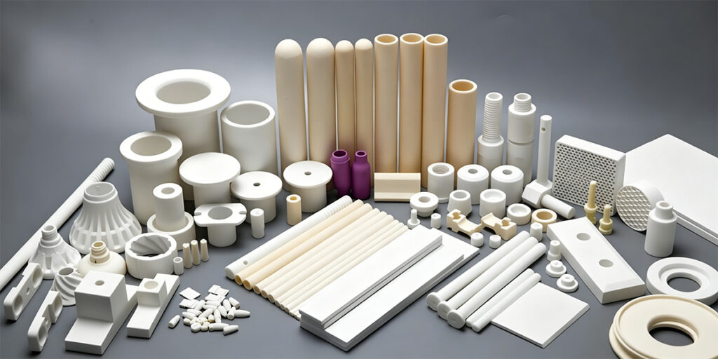
- Technical Ceramics (Alumina, Zirconia) — for medical implants and wear components
- Magnetic Materials (NdFeB, SmCo) — for motors and sensors
These materials appear across several high-value industries. Diamond wire cutting supports semiconductor wafering, photovoltaic silicon squaring, optical lens and prism sectioning, industrial ceramic part fabrication, and laboratory crystal sampling. For conductive metals requiring intricate internal features, Wire EDM serves as the complementary technology—but for brittle, non-conductive, or thermally sensitive materials, abrasive diamond wire remains the definitive manufacturing solution.
Wire Cutting vs Traditional Cutting Methods
In precision manufacturing, the choice between wire cutting, blade sawing, abrasive wheels, and laser systems directly impacts kerf economy, surface integrity, and overall part quality.
| Dimension | Wire Cutting | Blade Cutting | Abrasive Wheel | Laser Cutting |
| Kerf loss | 0.10–0.30 mm (diamond wire); EDM slightly wider | Wide, determined by blade thickness | Moderate to wide, increases as wheel wears | Narrow kerf, but accompanied by heat-affected zone |
| Precision | Micron-level positioning, minimal taper | Good for ductile metals; edge breakout on brittle stock | Moderate; often requires secondary grinding | High on thin sheet; limited on thick or reflective materials |
| Surface quality | Smooth, cold cut (diamond); EDM leaves recast layer | Rough edges on hard materials, burr formation common | Micro-cracking and chipping on brittle workpieces | Recast layer and dross; post-processing often required |
| Material suitability | Hard, brittle, non-conductive (Si, SiC, ceramics, glass, magnets); EDM for conductive metals | Metals, plastics, wood; fails on very hard materials | Hard metals, stone; risks thermal damage | Metals, some organics; struggles with thick or reflective stock |
| Cost efficiency | Strong for high-value workpieces where material savings matter | Fast and low-cost for high-volume simple cuts | Moderate cost; consumable wheel expense | High capital cost; excellent speed on thin sheet metal |
In short, wire cutting consistently outperforms traditional methods when sectioning hard, brittle, or thermally sensitive materials where kerf economy and surface integrity are non-negotiable. Blade and abrasive wheel cutting remain practical for high-volume work on ductile metals, while laser systems excel at rapid profiling of thin metallic sheets—but none match wire cutting for cold, low-damage processing of advanced materials.
Advantages and Limitations of Wire Cutting
Like any manufacturing process, wire cutting offers a distinct set of strengths and trade-offs. Evaluating both sides realistically helps engineers select the right technology for the job.
Advantages
- High Precision: Diamond wire and Wire EDM both deliver micron‑level positioning accuracy and minimal taper, suitable for tight‑tolerance components.
- Low Material Loss: Kerf loss as narrow as 0.10–0.30 mm (diamond wire) maximizes yield from expensive monocrystalline ingots.
- Minimal Chipping and Subsurface Damage: The abrasive cold‑cutting action produces clean, crack‑free edges—especially critical for brittle ceramics and semiconductors. Wire EDM avoids mechanical stress entirely.
- Wide Material Range (Diamond Wire): Handles hard, brittle, and non‑conductive materials including silicon, SiC, sapphire, glass, and rare‑earth magnets.
- Complex Internal Geometries (EDM): Wire EDM excels at intricate profiles and sharp internal corners in conductive metals, which abrasive wire cannot easily replicate.
- No Heat‑Affected Zone (Diamond Wire): The cold‑cutting nature preserves material microstructure and magnetic properties.
Limitations
- Slower Than Some Methods: Compared to laser cutting of thin sheet metal or waterjet of thick plate, wire cutting can be slower, limiting throughput for high‑volume simple cuts.
- Equipment Cost: Industrial‑grade wire saws and EDM machines represent significant capital investment. Multi‑wire systems increase cost further.
- Maintenance Requirements: Consumables (wire, guide rollers, filters, dielectric fluid) and tension‑system upkeep demand regular attention to maintain precision. Wire breakage interrupts production.
- Conductivity Constraint (EDM): Wire EDM only processes electrically conductive materials, excluding ceramics, glass, and many advanced substrates.
- Geometry Limitations (Diamond Wire): Standard abrasive wire setups are optimized for straight or large‑radius cuts; sharp internal corners require alternative approaches.
In practice, wire cutting remains indispensable when material integrity, narrow kerf, and low damage outweigh the need for maximum cutting speed. Understanding where its limits lie is just as important as appreciating its precision.
Future Trends in Wire Cutting Technology
The landscape of wire cutting is evolving rapidly, driven by the aggressive demands of the semiconductor and renewable energy sectors. As we look toward the future, the primary focus of innovation is centered on “doing more with less”—achieving higher yields while reducing waste.
One of the most significant trends is the development of thinner wires. Manufacturers are pushing the limits of materials science to produce high-tensile steel cores that allow for wire diameters well below 0.1mm. This transition is critical for reducing kerf loss in the silicon carbide (SiC) and gallium nitride (GaN) markets, where every micron of saved material translates into significant profit.
Furthermore, we are seeing a massive shift toward higher speed cutting enabled by Endless Wire Loop technology and advanced CNC integration. Real-time monitoring and AI-driven precision control are becoming standard, allowing machines to automatically adjust wire speed and tension based on sensor feedback. This level of automation not only boosts throughput but also reduces the likelihood of wire breakage, making the process more reliable for 24/7 industrial production. As industries move toward smarter factories, wire cutting is transforming from a standalone machining step into a fully integrated, data-driven manufacturing solution.
Wire cutting is a transformative technology for processing hard, brittle, or high-value materials where traditional methods fail. By balancing precision control with minimal kerf loss, it ensures maximum material yield and superior surface quality.
Need a specialized Diamond Wire Cutting solution for your project? [Contact our engineering team today] to discuss your material requirements or request a customized technical consultation.